Thursday, August 17, 2017

The Big Fan Swap

     During the summer months our living room was often the warmest part of the home so a few years back we decided to install a ceiling fan. At first the unit seemed to work out fine, but as the following summer rolled in that sentiment quickly changed.

We soon discovered that not only was the fan too small but in order to feel the airflow you had to be within close proximity or directly underneath the unit. The other factor, although not as important, was the color. No matter how much we wiped the blades they never seemed to look clean.

Before buying the ceiling fan we had researched units that would work well in 18' x18' spaces the range we were able to come up with was between 52 and 58-inches. Assuming the 52-inch would be enough we opted for the smaller and least expensive unit, partly due to budget constraints at the time.

After dealing with the undersized fan long enough, it was time to fix this mistake, once and for all. Going over our options this time around we focused on the larger ceiling fans, but while we were looking at our options two things stuck out at us. First of all 58-inch ceiling fans weren't very common which meant not a lot of choices.

The second thing was that since the 58-inch wasn't very common it came with a premium price tag.
Irritated, we decided to look at the 60-inch units since there were plenty of those. Right away we saw that the differences were obvious not only did the 60-inch come in slightly more efficient than the 58 but because we didn't need a light kit the unit was actually much cheaper.

 The choice was made, the 60-inch Monte Carlo in Roman Bronze would be our replacement.

Fast forward to this past weekend, the day the unit was delivered, it went up. Installation was a breeze. Since we already had an existing unit in place there was no need for any new wiring, switching or fan bracing. The process began by laying out all the parts for inventory.

Once all the parts were accounted for the circuit breaker went OFF and the old unit came down. With the old unit now out of the way the base mount for the new fan went up.

Quick note: Before installing any ceiling fan the junction box that supports the new unit must be secured in a way that will handle the weight of the fan. In most cases a ceiling fan brace is used. Never rely on the standard junction box that is nailed into the side of the ceiling joists.

The new ceiling fan gave us two options for installing, the flush mount which allow the units base to hug up to the ceiling, or hang slightly lower with the use of a down rod. To keep things simple we went with the flush mount.

Before the fan could be put up the canopy first needed to be attached to the top of the fan assembly. That meant removing three pan head screws where the canopy would sit and adding a rubber vibration gasket between the two pieces before securing the canopy in place.

Once the canopy was ready the next step was to wire the fan assembly to the wires in the ceiling junction box. Most fan assemblies come prewired with long wires coming out of the top of the assembly this is just in case your install requires a long down rod for example in the case of a vaulted ceiling. Since our unit was being flush mounted the wires back so to allow about 12 or so inches.

As I mentioned before a light kit was not needed so the light wire was capped at the top of the assembly and the remaining wires were spliced to the wires in the ceiling junction box. Once that was done the assembly was attached to the mount.

Next up was the fan blades. Before each could be installed the blades needed to be attached to individual brackets, with the help from my little assistant we attached the pieces together and put them aside.

Now to install the blades. Ceiling fans normally come with motor stabilizers,
basically a square rubber washers that sits in between the motor and fan assembly. Before each fan blade can be installed a couple of the stabilizers need to be removed. As each blade goes up another one comes out.

I've found that if you remove one stabilizer at a time it makes it easier to install the blades because you don't have to keep the motor from spinning.

Once the fan blades were all in the switch housing was the last thing to go on. This is the bottom piece of the fan assembly with the fan speed chain coming out of it. If the ceiling fan has a light kit this is where it would be installed in place of the switch housing.

With the new ceiling fan now completely installed it was time to test our work. Circuit Breaker back ON, I turned the wall switch ON and pulled the ceiling fan chain.

Quick note: In most instances, a new ceiling fan leaves the manufacturer in the OFF position. Once the new unit is installed just give the fan chain a single pull and do the same for the light, if it applies. If the unit has a remote simply follow the manufacturer instructions to sync the remote to the remote module.

With the fan now fully running I left the unit at its highest speed so that we could now control the unit with our Ceiling Fan wall switch.

This particular ceiling fan took just over an hour to install if this had been a completely new install the project would of taken much longer. How much longer would of course depend on the location, switching availability, type of switching and accessibility.

Key factors to know before installing a ceiling fan:

1) Make sure the placement of the fan is such that the blades are at least 18 inches from any wall or obstruction. The ideal place is center of the room but not everyone's needs are the same so always measure.

2) In the case of a vaulted ceiling, make sure the fan is not installed on a pitch more than 30 degrees.

3) Switching can be a little overwhelming so to help simplify some common options: wall switch controlled, fan controlled, remote controlled or any combination of the three.

4) I know I've mentioned it already but I cant stress this enough, a ceiling fan brace is very important and should be a apart of every fan install. Relying on a plastic box that is nailed to the side of the ceiling joist should never be an option.

Well I hope you've enjoyed this article if you have any questions or comments feel free to share them below. Look for my next article where I share my experiences on balancing a ceiling fan. Until next time.



Thursday, June 22, 2017

Lighting Nuisance

     Every now and then an electrical issue surprises me. Sometimes its because of where the trouble is located, other times, its due to the extent at which the problem has spread.

But in a recent experience the thing that surprised me most about the situation was how ridiculously easy the trouble was to fix. I'll explain.

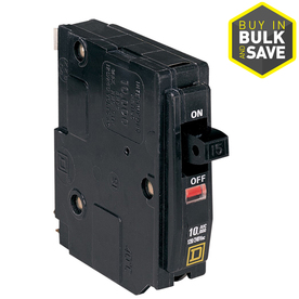
The problem began with a circuit breaker tripping, thats when an internal safety feature is triggered inside the breaker and power is instantly cut off. According to the homeowners this started just after the backyard light fixture was replaced.

After gathering a little more information I began my troubleshooting at the obvious place first, the new light fixture.

Once the fixture was removed I checked for any indication of a problem. I looked at the wires, wire-nuts, back of the fixture, and the internal space of the junction box the fixture was attached to. Nothing.

The cause of the tripped circuit breaker was not the new light fixture, it was clear that an important clue had somehow been missed. Whenever an electrical problem comes up it usually follows one or more clues just before it fails.

 With little else to go on the next step was to go through and systematically rule out likely causes along the circuits path. From one junction point to another I checked for any signs of arcing, soot and burnt plastic smells.

With the above now scratched off the list I focused on the bedroom switches and fan/ light fixtures. Why? Because it was the only things left.

Since the Master bedrooms switch junction box contained the wiring for both bedrooms I decided to isolate and test the adjoining room first. With the circuit breaker OFF and Master bedroom wires removed the adjoining room was ready.

Power back ON I was able to get the ceiling fan and its lights working without any trouble, I then turned ON the backyard light to see if this would trigger the problem. Nothing. Everything seemed to work fine.

With the circuit breaker OFF again the adjoining bedrooms wires were removed and the Master bedrooms wires were connected. The circuit breaker was turned back ON and quickly shut OFF. The problem was now isolated to the Master bedroom.
 
Leaving the switch connected and the breaker in the tripped mode I next focused on the wires between the switch and fan/light fixture.

The Fan/ light fixture had a remote control receiver that was wired in at the ceiling junction box, after carefully removing it I decided at the last minute to remove the fan/ light fixture altogether.

With everything out of the way, I tested again. No trip. With power and the Master bedroom switch still ON, the backyard light fixture was also turned ON. No trip.

 With the power back OFF,  I reinstalled the ceiling fan but this time wired it without the receiver. The goal was to do a quick test. Power back ON, I ran through every sequence I could think of to get the circuit breaker to trip, but it wouldn't. The only thing removed from the original equation was the remote receiver.

The problem had now appeared to be found. The homeowners decided they could live without the remote so I closed everything up and left. My accomplishment was short lived, within a few hours the problem would return.

A little frustrated, I returned to the home and pulled the Master bedroom fan/ light fixture, apart. I retraced my steps and went over every detail, I double and triple checked my work to see if anything had changed, it hadn't.

Since I was now confident as to where the problem was I left the switches alone and allowed the wires in the junction box to stay connected. With the circuit breaker reset, I tested the bedroom light. Just like before the power shut off instantly. Without hesitation I went back out and reset the circuit breaker, I forgot to turn OFF the light switch in the Master Bedroom so when the breaker reset the light immediately came ON.

During the entire process I hadn't thought to leave the switch ON, seeing an opportunity I decided to run through a test. With the Master Bedrooms light still ON I went over to the adjoining bedroom and turned the lights on. No trip.

I went over to the backyard light switch and turned it ON. Still no trip.

Back in the Master bedroom I turned the switch OFF and ON sure enough the breaker tripped. Leaving the switch ON again I reset the breaker and this time tried controlling the fan/ light fixture using the pull chains attached to the fixture.

When I pulled one of the chains the circuit breaker tripped, but just before it did that two very distinct things happened. First, the light assembly at the bottom of the fixture was noticeably loose so when I pulled down the light assembly shifted sideways.

The second thing that happened was one of the bulbs flickered.

In disbelief, I quickly unscrewed the light assembly and checked the wiring harness when nothing was found I put the light assembly back and secured it properly.

Now that the light assembly was taken care of I moved on to the bulbs themselves. I recall seeing two bulbs and one of them flickering just before the breaker shut off. Well the funny thing was that this particular fixture had three bulbs.

Still in disbelief but eager to get this resolved I reached up and snugged down all three bulbs. For good measure I went into the adjoining room and did the same with those bulbs. When I turned the circuit breaker on this time everything on the circuit stayed ON.

So what was the problem exactly? Loose bulbs. Thats right loose bulbs but thats not the whole story you see normally a standard circuit breaker wouldn't flinch at a small arc like those you may find in a uh oh I don't know lets say loose bulb. But, the homeowners didn't have a standard circuit breaker they had what is called an Arc Fault Circuit Interrupter or AFCI.

AFCI's were put in place to help prevent small arcs from becoming big problems, unfortunately they don't decipher between a loose plug in an outlet and a loose bulb in a light socket.

Because of electrical code requirements AFCI's are going to be the industry standard, with that said, some of the ways homeowners can help avoid this situation is by being more informed and aware of the things that cause this type of trouble.

For those of you reading this article you can scratch that off your list.

The next thing you can do is home maintenance, if you know a bulb is flickering check it out and if need be, replace it. Another thing that led to this problem was an unbalanced ceiling fan, if your have a fan/ light fixture and its noticeably wiggling do some online research and find out how its supposed to work.

If your handy you can learn how to balance the ceiling fan yourself, its not hard and most anyone can do it themselves in a short period of time.

I hope you've enjoyed the article if you have any questions or comments feel free to share them below. Until next time be safe.


Friday, April 1, 2016

The Lorex Setup

         Recently I installed a surveillance system for a family eager to finish the last of their homes security system. Their must-have list was simple, they wanted a complete view of the homes perimeter and access to the footage via the internet. The solution, an all-in-one Lorex that provided eight high definition cameras and a DVR that easily connected to the homes network.

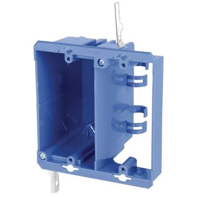
After finalizing camera placement, DVR location, and a few other details the installation was ready to begin. First up, cutouts for the junction boxes. Since the monitor and DVR would not be in the same location the project would need two junction boxes. The first cutout was made behind where the monitor would sit, the other, near the DVR's location.

Once the cutouts were completed holes for the BNC, HDMI, and Romex cables were drilled up through the wall cavity, into the attic. The BNC cables would bring the video from each camera to the DVR while the HDMI cable sent the combined footage to the monitor from the DVR. The Romex cable would supply power for all the equipment.

The HDMI and Romex cables were run from one junction box opening to the other; at the DVR's location the Romex cable was continued on to an existing junction box where power would later be tapped.

Next was the router connection, the Cat5e cable was simply a must in order to access the DVR footage over the internet. Using a nearby wall mounted phone jack we shared the access point and ran the Cat5e cable over from the DVR's location down through the opening. The phone
and data cables were terminated to keystone jacks for a much cleaner look then snapped into a dual port insert. We attached the insert over the access point to close it up and connected the patch cables to their respective places. The Cat5e cable was now in.


Back at the monitors location the Romex and HDMI cable were taken from the wall cavity and placed into the junction box, the junction box was then inserted into the cutout and the corner tabs screwed down until the box was fastened to the wall. Once the HDMI cable was passed through the
insert the outlet was wired-in. The insert and outlet were attached to the junction box and the cover plate installed. On to the next step.

Now for the wall mount. After finalizing height and mount measurements the stud was pre-drilled for the lag bolts that would anchor the base to the wall. Using a 1/2" socket wrench the lag bolts were attached to the mount and screwed down until the base was firmly secured to the wall.

The other half of the mount was attached to the back of the monitor, however there was a problem. Though the mount lined up perfectly to the monitor the mounts solid design prevented the power cord from connecting to the monitor. To fix this we drilled a large enough hole through the mount to fit the head of the cord. Twenty minutes later the mount was reattached and the power cord plugged in. The monitor and mount were latched onto the arm assembly of the base and locked in place. The monitor and all its equipment were now in.

We could now install the cameras and BNC cables. Quick note: before hanging each camera unwind the BNC cable and plug the camera end in first so as not to run the wrong end to the DVR.

Holes for the cable and camera mounts were drilled with either a masonry bit or wood and paddle bit, it just depended on where the camera was being installed. Because the BNC video connectors outer diameter holes needed to be a minimum of 5/8 inch. Camera mounts covered most of the holes, but where they didn't we filled it with 100% silicone.


As each camera was installed the BNC cables were brought back to the DVR, once all eight cameras and cables were in place the second junction box was installed. Just as before, cables were passed through and the corner tabs were screwed down until the junction box was fastened to the wall. The insert and outlet were attached to the junction box and the cover plate finished the look off.

Now that both outlets were wired-in and installed we shut off power to room and connected the Romex cable to the room circuit that it was left in earlier. That junction box was closed back up and power turned back ON, the outlets were tested and now ready to be used.

All the cables to the DVR were connected and the surveillance system turned ON. Adjustments had to be made to each camera until the homeowner was satisfied with all eight angles. The online portion was left to the homeowners since they wanted to do that part themselves; later that evening they called back and let me know that they were streaming the video through their phones via the home network. The project was now complete.


This particular project took a little more than a day from start to finish but if you plan on tackling a similar project there are a few factors to keep in mind.

1) Know how many cameras you need. Give yourself an even coverage of your home if not focus on the key areas like the front door, garage, Side garage door if your home has one, and the backyard door.

2) Know where your equipment will go. Make it difficult to find dont just have the DVR sitting out in the open.

3) The best places dont always have power nearby so figure out how you will get power to your equipment and factor in the extra cost. Running an extension cord is not a long term solution if your DVR is in an isolated location, have an electrician install an outlet for you.

4) And finally, have a backup plan, dont depend primarily on just the DVR to store the recorded footage have a place to store the old footage. This can be a flash drive, external hard drive or even the cloud.

I hope you've enjoyed reading this article if you have any questions or comments feel free to leave them below. Until the next one.

Wednesday, February 3, 2016

Overloaded

        A friend called the other day about an electrical issue she was having, the power in her living room had gone out and she really needed help getting it working again. She assured me that the problem only affected the one area of her home, the rest of the place was fine.

Since the problem was confined to the living room we began there. The situation occurred while my friend was vacuuming the living room carpet, knowing that a vacuum cleaner was not enough to trigger a loss of power, I decided to ask if any other appliances had been ON at the time of the outage. She said yes. In addition to the vacuum cleaner, there was the television, a cell phone that was charging on the end table, oh and a small portable heater.

One common misconception we tend to have is if an appliance is small, its power usage must also be small, but this isn't always the case. Take for instance, appliances with heating elements and small motors, these units can use up to 60% or more of a circuits power just to operate- regardless of size.

With the list of potential causes now known I asked my friend to find me the electrical specs of each appliance, I needed to check the combined values to see what the overall usage looked like. After reviewing the specs I determined that two of the appliances were likely the cause of the power failure. I had my friend unplug the vacuum cleaner and turn the portable heater OFF, that way both appliances wouldn't interfere with resetting the circuit breaker.

Next, I had my friend head to the Electrical Panel all the while, explaining how to identify a tripped circuit breaker:

(1) Look for the toggle switch of a circuit breaker to be midway between On and Off see circuit #13
(2) If the circuit breaker has an indicator window, it will be red
(3) in some cases the toggle switch will appear to be OFF, so look for the one with the slightest difference and gently wiggle the toggle switch. If there is no tension that will be the tripped circuit breaker.

Once she located the correct toggle switch, I then explained how to reset the circuit breaker:

Push the toggle switch towards the OFF position until it clicks and locks in place. Then push the toggle switch in the opposite direction until it locks to the ON position. Since the toggle switch remained in place my friend went back to the living room and confirmed that the electricity had been restored. I explained that if she wanted to continue vacuuming she needed to keep the portable heater off and never have both appliances running in the same room at the same time.

When most people experience an overload they skip right to the resetting the breaker part, but then when the circuit breaker stops resetting, or starts shutting off periodically, they don't understand why. Resetting a circuit breaker without dealing with the cause first is a short term gain, take the time needed to properly find the cause and minimize the chances of losing the circuit breaker altogether.  

Important Note: When resetting a Circuit Breaker ALWAYS remove the cause of the overload before you reset the device so as not to damage the circuit, devices, or any other equipment. If a circuit breaker does not reset or immediately shuts off after resetting, STOP and DO NOT reset again. Schedule a licensed Electrician to come out and troubleshoot the problem further.

Until next time, stay safe.


Wednesday, January 6, 2016

Know Your Arc Faults Part 5

       The last dangerous arc fault in our series also happens to be one of the most elusive, they tend to develop in areas of the home that are closed off and difficult to reach. When this form of arc fault does reveal itself the aftereffects are often devastating.

This particular type of arc fault is usually a result of damaged Circuit Conductors, circuit conductors are the wires that travel from the Electrical Panel to specific junction points e.g., outlets, switches and dedicated appliances.

A circuit conductor can become damaged in a number of ways, but the most common are; during installation, while drilling or screwing through a wall, and from rodents chewing on them.

Because of the location of the circuit conductors, the only true method for protection against this type of arc fault is an Arc Fault Circuit Interrupter or AFCI. An AFCI is an electrical device that differentiates between normal and dangerous arc faults, once a dangerous arc fault is detected power to the circuit is shut off. 

There are two options available for AFCI protection, the first is a combination AFCI circuit breaker that must be installed at the Electrical Panel. This is the preferred option since the device is able to protect the entire circuit. The second option is an AFCI outlet. This device must be installed at the first junction point of the circuit in order to be effective. The only part of the circuit that won't be protected is the conductor that travels from the Electrical Panel to that first junction point.  


Knowing the dangerous arc fault potentials in your home is an important first step in reducing the risk of occurrence, but the biggest factor in protection is you.  

 I hope you've enjoyed this five part series of Know Your Arc Faults, if you have any questions or comments feel free to share them in the comments section below. Until next time.
Monday, December 7, 2015

Bathroom Exhaust Fan

         The old exhaust fan in our bathroom was on its last leg, after years of noisy inefficient venting it was time to put this energy hog to rest. 


Before going out and buying a new exhaust fan we had to first figure out what CFM value was right for our space. Taking the bathrooms length, width, and height, we multiplied the three to find the cubic footage of the area (LxWxH= cu.ft.). Using a Bathroom Fan Sizing Chart, we matched our measurement to the recommended CFM value. Now we knew exactly what to look for.

There were three factors guiding our purchase of a new exhaust fan. First, the unit had to be energy efficient. An exhaust fan removed moisture and unpleasant odor, it should not require a lot of energy to accomplish this. Second, the unit had to be silent. With quieter well built exhaust fans these days there was no reason to settle for anything less. And finally, the fan had to be reasonably priced. The unit that best met these points was the Panasonic Whisper Ceiling.

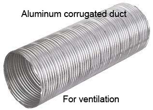
With the replacement unit now chosen it was time to look at the existing ductwork. During inspection of the four inch corrugated duct we found areas that were punctured, compressed and pulled apart. It was clear the existing system would have to go. 

The question now was, do we replace the existing ductwork with another four inch corrugated duct, or look for an alternative. After some online research and a call to a contractor friend we decided to go with a six inch smooth-tubed duct. Both the increase in size and the smoother inside would benefit the new exhaust fans performance.

Next, we had to determine where the six inch duct would be venting out at. Since the system had to exhaust directly to the outdoors aiming the ductwork to the nearest roof, eaves or gable vent wouldn't of been sufficient. The overall duct length was also important, having the total length remain as short as reasonably possible was necessary to avoid condensation in the line.

We would vent through the roof. To carryout this part of the process we went with a simple product called a roof cap. The roof cap provided a duct collar on the underside of the housing and was equipped with a secondary backdraft damper; keeping insects, critters and outside air from coming in.

The final missing piece of the new system was a switch. The existing system had originally been wired to the bathroom lights, so when the fan was on, so were the lights. The new switch would have to come on when a person entered the bathroom and remain on long enough for showers when needed. The solution, an occupancy sensor switch. 

After everything was ordered and delivered demo was ready to begin. Bathroom power was shut off and the ceiling was taken down. Most exhaust fan installations DO NOT require removal of the ceiling, but because of mold and brittle drywall, the ceiling had to come down. The old exhaust fan and ductwork followed, after a lengthy clean up all traces of the old system were gone.

Before installing the new unit we had to mount the sliding brackets to the housing; the side that didn't have brackets was screwed to the underside of the ceiling joist while the other was secured to the adjoining ceiling joist.  

With the fan housing now firmly in place we were ready for the new ductwork. A twenty-four inch piece of duct was attached to the housing from there a 90 degree elbow was added, followed by the riser that would eventually connect to the roof cap. The pieces were temporarily assembled so we could mark the underside of the roof and make the cut for the new roof cap. 


Once the roof cap was installed the ductwork was reassembled for good. An aluminum joint tape was applied to lock all the ductwork together and seal the seams. We used a plastic putty knife to flatten down any remaining ripples in the joint tape; the putty knife was especially helpful around the 90 degree elbow seams that were harder to reach.  

One of the biggest complaints about roof cap venting was outdoor noise echoing down the duct, so at the last minute we added a six inch duct insulation sleeve to help deaden some of those sounds. The top and bottom ends of the sleeve were also taped to keep it from sliding, the duct was then strapped to the rafter with a brace.

Once the ductwork was completed it was time to wire the exhaust fan. Opening the junction box, we removed one of the 1/2" concentric knockouts and inserted the snap-in bushing that came with the fan. The new conductors were then run through the bushing and each was wired to its respective place. Power to the bathroom was turned on so we could test the exhaust fan and help blow out any dust that accumulated inside, during installation.   

The new exhaust fan worked perfectly. With power off again the occupancy sensor switch was then installed and adjusted using the schematics diagram that came with the switch. A bead of caulk was applied to the bottom opening of the exhaust fan housing and the ceiling drywall was installed. Normally caulk is applied on the back of the drywall in the attic but because our ceiling was removed we had to apply it from underneath. 


I Hope you've enjoyed the article if you have any questions or comments please leave them below. On to the next.


Monday, October 26, 2015

Know Your Arc Faults Part 4

      Along the highway of conductors that run in and around our home, travels the one element to help transform daily chores into simple tasks. 

But before this modern miracle can take place the source must first reach its destination. Its here at the connection point or junction box where dangerous arc faults can occur.

The primary reasons for dangerous arc faults in a junction point are improper splicing, misuse of wiring fasteners, and/or the wires are aluminum.  

So what should you look out for. 

The first indicator of a potential problem at a junction box is faint to dark soot marks on the face and cover of an outlet or switch.

Although this can be misdiagnosed as a failing wall outlet or switch this is why its so important to resolve an electrical issue sooner rather than later.   

The indicator for light fixtures is similar, soot marks will accumulate around the outside of the fixture, surrounding the base of the fixture and leaving a faint ring or trail depending on how the fixture is mounted.

The last clue although not very common, is probably the most serious. The sharp burning smell of plastic. This strong but distinct odor is a clear sign that the splicing and insulation of the conductors within the junction box and/or walls may have begun to melt. 

If you encounter this smell call 9-1-1 immediately.  
        
Identifying these hidden electrical arc faults can sometimes be a challenge, but as you now know each provide advanced warnings before they get out of hand.

Please read on to our final article of the series, Know Your Arc Faults part five.